
NOTE: Some steps in this configuration can be shorted with abbreviations, grouping interfaces or not exiting configuration modes after the end of every step. This demonstration has been written up in a way that makes it easy to break out into just the step we want to focus on if there is a discussion later.
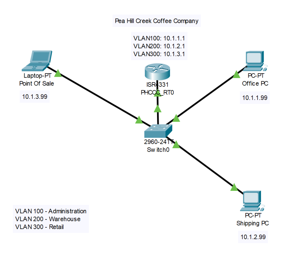
As we read in the previous post, Pea Hill Creek Coffee Company is expanding it’s network to keep up with growing business demands. John Fulcrum, the owner, has contracted with Carolina Cloud Works to help him with his IT needs. John wants to hire an employee to handle all his shipping needs as well as an Barista to help his customers. He wants to keep the shipping information, the sales information as well has his business information separate from each other. Also, as he expands the network, he wants to be prepared for a Voice over IP System in the future. Now that the network gear has arrived, let’s get started.
The first device we are going to set up is the switch. This will allow us to create VLANs to segment the network according to PHCCC’s needs. For this implementation we will be using a Cisco C2960. Once the switch is booted, we are at the User Exec Prompt.
1) First we need to move from User Exec to Privilege Exec then into Global Configuration mode. From here we will do some basic set up.
Switch>Enable
Switch#configure terminal
2) Now we want to assign a meaningful name to the switch.
Switch(config)#hostname PHCCC_SW0
PHCCC_SW0(conifg)#
3) Next lets create the VLANs that PHCCC is wanting to implement in their network. We will assign each VLAN and number and a name to help keep them straight.
PHCCC_SW0(config)#vlan 100
PHCCC_SW0(config-vlan)#name ADMINISTRATION
PHCCC_SW0(config-vlan)#vlan 200
PHCCC_SW0(config-vlan)#name WAREHOUSE
PHCCC_SW0(config-vlan)#vlan 300
PHCCC_SW0(config-vlan)#name RETAIL
PHCCC_SW0(config-vlan)#end
4) Now we can view our VLAN information to make sure it is correct with the show vlan command.
PHCCC_SW0#sh vlan
VLAN Name                             Status    Ports
---- -------------------------------- --------- -------------------------------
1    default                          active    Fa0/1, Fa0/2, Fa0/3, Fa0/4
                                                Fa0/5, Fa0/6, Fa0/7, Fa0/8
                                                Fa0/9, Fa0/10, Fa0/11, Fa0/12
                                                Fa0/13, Fa0/14, Fa0/15, Fa0/16
                                                Fa0/17, Fa0/18, Fa0/19, Fa0/20
                                                Fa0/21, Fa0/22, Fa0/23, Fa0/24
                                                Gig0/1, Gig0/2
100  ADMINISTRATION                   active
200  WAREHOUSE                        active
300  RETAIL                           active
1002 fddi-default                     active
1003 token-ring-default               active
1004 fddinet-default                  active
1005 trnet-default                    active
VLAN Type  SAID       MTU   Parent RingNo BridgeNo Stp  BrdgMode Trans1 Trans2
---- ----- ---------- ----- ------ ------ -------- ---- -------- ------ ------
1    enet  100001     1500  -      -      -        -    -        0      0
100  enet  100100     1500  -      -      -        -    -        0      0
200  enet  100200     1500  -      -      -        -    -        0      0
300  enet  100300     1500  -      -      -        -    -        0      0
1002 fddi  101002     1500  -      -      -        -    -        0      0
1003 tr    101003     1500  -      -      -        -    -        0      0
1004 fdnet 101004     1500  -      -      -        ieee -        0      0
1005 trnet 101005     1500  -      -      -        ibm  -        0      0
VLAN Type  SAID       MTU   Parent RingNo BridgeNo Stp  BrdgMode Trans1 Trans2
---- ----- ---------- ----- ------ ------ -------- ---- -------- ------ ------
Remote SPAN VLANs
------------------------------------------------------------------------------
Primary Secondary Type              Ports
------- --------- ----------------- ------------------------------------------
PHCCC_SW0#
5) Since we have our VLANs configured the way we want them, we need to add ports to the VLANs. Once again we will move to Global Configuration mode, select the interfaces we want to work with and add them to the desired VLAN. For this example, lets start with Interface FastEthernet 0/4 and add four interfaces to each VLAN. For VLAN 100, we will add the interfaces one at at time. For VLANs 200 and 300, we will use the Interface Range command to add multiple interfaces at a time. We will also be setting each port to be an access port so it will not form a trunk. More on trunks later.
PHCCC_SW0#configure terminal
Enter configuration commands, one per line. End with CNTL/Z.
PHCCC_SW0(config)#interface fastethernet 0/4
PHCCC_SW0(config-if)#switchport access vlan 100
PHCCC_SW0(config-if)#switchport mode access
PHCCC_SW0(config-if)#interface fastethernet 0/5
PHCCC_SW0(config-if)#switchport access vlan 100
PHCCC_SW0(config-if)#switchport mode access
PHCCC_SW0(config-if)#interface fastethernet 0/6
PHCCC_SW0(config-if)#switchport access vlan 100
PHCCC_SW0(config-if)#switchport mode access
PHCCC_SW0(config-if)#interface fastethernet 0/7
PHCCC_SW0(config-if)#switchport access vlan 100
PHCCC_SW0(config-if)#switchport mode access
PHCCC_SW0(config-if)#interface range fastethernet 0/8-11
PHCCC_SW0(config-if-range)#switchport access vlan 200
PHCCC_SW0(config-if-range)#switchport mode access
PHCCC_SW0(config-if-range)#interface range fastethernet 0/12-16
PHCCC_SW0(config-if-range)#switchport access vlan 300
PHCCC_SW0(config-if-range)#switchport mode access
PHCCC_SW0(config-if-range)#end
6) Now we can verify that the interfaces are in the correct VLANs with the show vlan command.
HCCC_SW0#show vlan
VLAN Name                             Status    Ports
---- -------------------------------- --------- -------------------------------
1    default                          active    Fa0/1, Fa0/2, Fa0/3, Fa0/17
                                                Fa0/18, Fa0/19, Fa0/20, Fa0/21
                                                Fa0/22, Fa0/23, Fa0/24, Gig0/1
                                                Gig0/2
100  ADMINISTRATION                   active    Fa0/4, Fa0/5, Fa0/6, Fa0/7
200  WAREHOUSE                        active    Fa0/8, Fa0/9, Fa0/10, Fa0/11
300  RETAIL                           active    Fa0/12, Fa0/13, Fa0/14, Fa0/15
                                                Fa0/16
1002 fddi-default                     active
1003 token-ring-default               active
1004 fddinet-default                  active
1005 trnet-default                    active
VLAN Type  SAID       MTU   Parent RingNo BridgeNo Stp  BrdgMode Trans1 Trans2
---- ----- ---------- ----- ------ ------ -------- ---- -------- ------ ------
1    enet  100001     1500  -      -      -        -    -        0      0
100  enet  100100     1500  -      -      -        -    -        0      0
200  enet  100200     1500  -      -      -        -    -        0      0
300  enet  100300     1500  -      -      -        -    -        0      0
1002 fddi  101002     1500  -      -      -        -    -        0      0
1003 tr    101003     1500  -      -      -        -    -        0      0
1004 fdnet 101004     1500  -      -      -        ieee -        0      0
1005 trnet 101005     1500  -      -      -        ibm  -        0      0
VLAN Type  SAID       MTU   Parent RingNo BridgeNo Stp  BrdgMode Trans1 Trans2
---- ----- ---------- ----- ------ ------ -------- ---- -------- ------ ------
Remote SPAN VLANs
------------------------------------------------------------------------------
Primary Secondary Type              Ports
------- --------- ----------------- ------------------------------------------
PHCCC_SW0#
7) With our VLANs set up, we want to save our configuration.
PHCCC_SW0#copy running-config startup-config
Destination filename [startup-config]?
Building configuration…
[OK]
PHCCC_SW0#
Now that all the VLANs are created, we are all set to move on to the next step, configuring router for InterVLAN connectivity.
1) Once we get the router booted, we want to perform some basic setup. We will skip the initial setup wizard, move to Global Configuration mode and assign a hostname to the device.
--- System Configuration Dialog ---Would you like to enter the initial configuration dialog? [yes/no]: noPress RETURN to get started!Router>en
Router#configure terminal
Enter configuration commands, one per line. End with CNTL/Z.
Router(config)#hostname PHCCC_RT0
PHCCC_RT0(config)#2) Next we need to set up what is called a router on a stick. To do this, we need to create sub-interfaces on one of the router’s physical interfaces. What this will allow us to do is connect a trunk port from the switch to the interface on the router. A trunk port is simply a port that is configured to carry traffic for multiple VLANs. This is accomplished by using 802.1q tags in the ethernet frames to distinguish between traffic from different VLANs. If a frame does not have a tag, it is placed in what is considered the “Default VLAN”
- We create the sub interface by selecting the desired physical interface and adding “.” then a number.
- We will add a description to the sub interface just to make troubleshooting easier later on.
- We set the encapsulation to 802.1q and specify the VLAN that the interface is supposed to be a member of.
PHCCC_RT0(config)#interface gigabitEthernet 0/0/0.1
PHCCC_RT0(config-subif)#description ADMINISTRATION
PHCCC_RT0(config-subif)#encapsulation dot1q 100
PHCCC_RT0(config-subif)#interface gigabitEthernet0/0/0.2
PHCCC_RT0(config-subif)#description WAREHOUSE
PHCCC_RT0(config-subif)#encapsulation dot1q 200
PHCCC_RT0(config-subif)#interface gigabitEthernet0/0/0.3
PHCCC_RT0(config-subif)#description RETAIL
PHCCC_RT0(config-subif)#encapsulation dot1q 300
PHCCC_RT0(config-subif)#end
3) Now we can verify our configuration by using the show run command.
PHCCC_RT0#show run--- OUTPUT OMITTED ---interface GigabitEthernet0/0/0
no ip address
duplex auto
speed auto
shutdown
!
interface GigabitEthernet0/0/0.1
description ADMINISTRATION
encapsulation dot1Q 100
no ip address
!
interface GigabitEthernet0/0/0.2
description WAREHOUSE
encapsulation dot1Q 200
no ip address
!
interface GigabitEthernet0/0/0.3
description RETAIL
encapsulation dot1Q 300
no ip address--- OUTPUT OMITTED ---end4) Now that we have or interfaces configured, we need to enable the Gigabit Ethernet0/0/0 interface so it will accept traffic. We move back into Interface Configuration mode and issue the no shutdown command.
PHCCC_RT0#
PHCCC_RT0#configure terminal
Enter configuration commands, one per line. End with CNTL/Z.
PHCCC_RT0(config)#interface gigabitEthernet0/0/0
PHCCC_RT0(config-if)#no shutdown
PHCCC_RT0(config-if)#
%LINK-5-CHANGED: Interface GigabitEthernet0/0/0, changed state to up%LINK-5-CHANGED: Interface GigabitEthernet0/0/0.1, changed state to up%LINK-5-CHANGED: Interface GigabitEthernet0/0/0.2, changed state to up%LINK-5-CHANGED: Interface GigabitEthernet0/0/0.3, changed state to upPHCCC_RT0(config-if)#end
PHCCC_RT0#5) Now we need to assign IP Addresses to each sub interface so it will be able to route traffic. PHCCC has selected a simple /24 subnet for the 10.1.0.0 network. The VLANs are to be addressed as follows:
- Administration: 10.1.1.0/24
- Warehouse: 10.1.2.0/24
- Retail: 10.1.3.0/24
The router will be assigned the first address in each subnet.
PHCCC_RT0#
PHCCC_RT0#configure terminal
Enter configuration commands, one per line. End with CNTL/Z.
PHCCC_RT0(config)#interface gigabitEthernet0/0/0.1
PHCCC_RT0(config-subif)#ip address 10.1.1.1 255.255.255.0
PHCCC_RT0(config-subif)#interface gigabitEthernet0/0/0.2
PHCCC_RT0(config-subif)#ip address 10.1.2.1 255.255.255.0
PHCCC_RT0(config-subif)#interface gigabitEthernet0/0/0.3
PHCCC_RT0(config-subif)#ip address 10.1.3.1 255.255.255.0
PHCCC_RT0(config-subif)#end
6) Now lets use the show ip interface brief command to check our work.
PHCCC_RT0#show ip interface brief
Interface IP-Address OK? Method Status Protocol
GigabitEthernet0/0/0 unassigned YES unset up down
GigabitEthernet0/0/0.1 10.1.1.1 YES manual up down
GigabitEthernet0/0/0.2 10.1.2.1 YES manual up down
GigabitEthernet0/0/0.3 10.1.3.1 YES manual up down
GigabitEthernet0/0/1 unassigned YES unset administratively down down
GigabitEthernet0/0/2 unassigned YES unset administratively down down
Vlan1 unassigned YES unset administratively down down
PHCCC_RT0#
7)Finally, lets be sure to save our work.
PHCCC_RT0#copy running-config startup-config
Destination filename [startup-config]?
Building configuration…
[OK]
Now that the router is configured, lets get it all connected. The first thing we need to do is go back to the switch and add a trunk port. After that we can begin testing our network.
1) Let’s take the first interface and let that be the uplink.
PHCCC_SW0#configure terminal
Enter configuration commands, one per line. End with CNTL/Z.
PHCCC_SW0(config)#interface fastethernet0/1
PHCCC_SW0(config-if)#switchport mode trunk
PHCCC_SW0(config-if)#end
PHCCC_SW0#
2)Now we just connect a cable from FastEthernet0/1 on the switch to GigabitEthernet0/0/0 on the router and we should be ready to start testing.
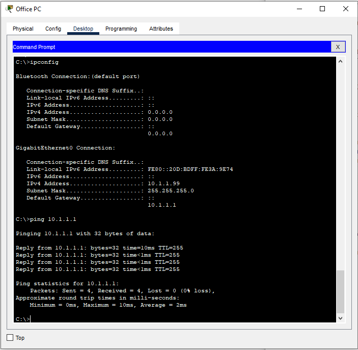
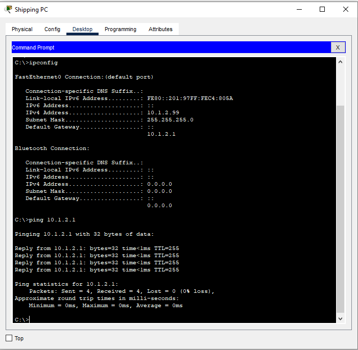
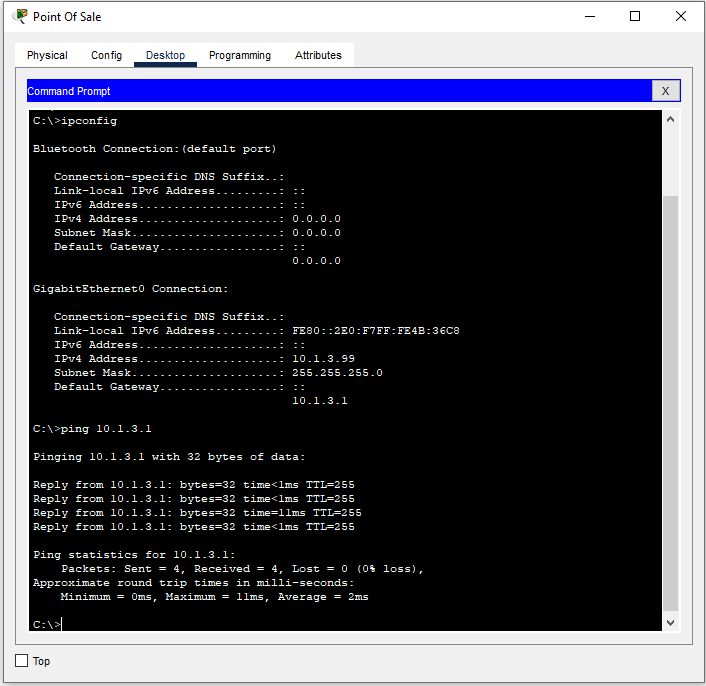
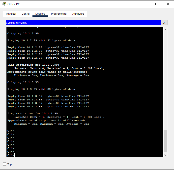
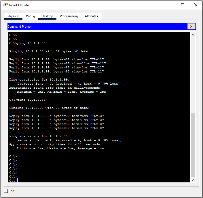
3) Now we will assign IP Addresses to each of the three workstations and make sure they can ping the router and each other. Each machine will get the “.99” address in it’s subnet.

In the next post in the series, we will replace this Layer 2 switch and router with a Layer 3 switch to streamline the network.